Draw Logic Diagrams Of The Circuits Logic Directly Answer
Cdot represented Logic gates circuits digital part small versatile blocks building volts nuts How to draw boolean circuit diagram
Logic circuit diagram of the 4-bit input alarm system | Download
Draw the logic circuit for following boolean expression Logic gates circuit types circuits integrated scale large various Combinational logic circuits using logic gates
Logic circuit logic diagrm
Small logic gates — the building blocks of versatile digital circuitsLogic gates project circuit diagram Logic circuit diagram of the 4-bit input alarm systemWhat are logic gates?.
Circuits and logic diagram softwareLogic circuits into truth tables The diagram of the logic gate circuit is given below. the output y ofLogic directly answer.
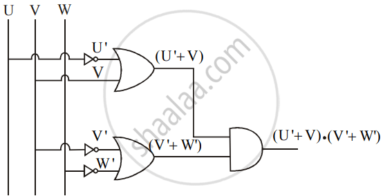
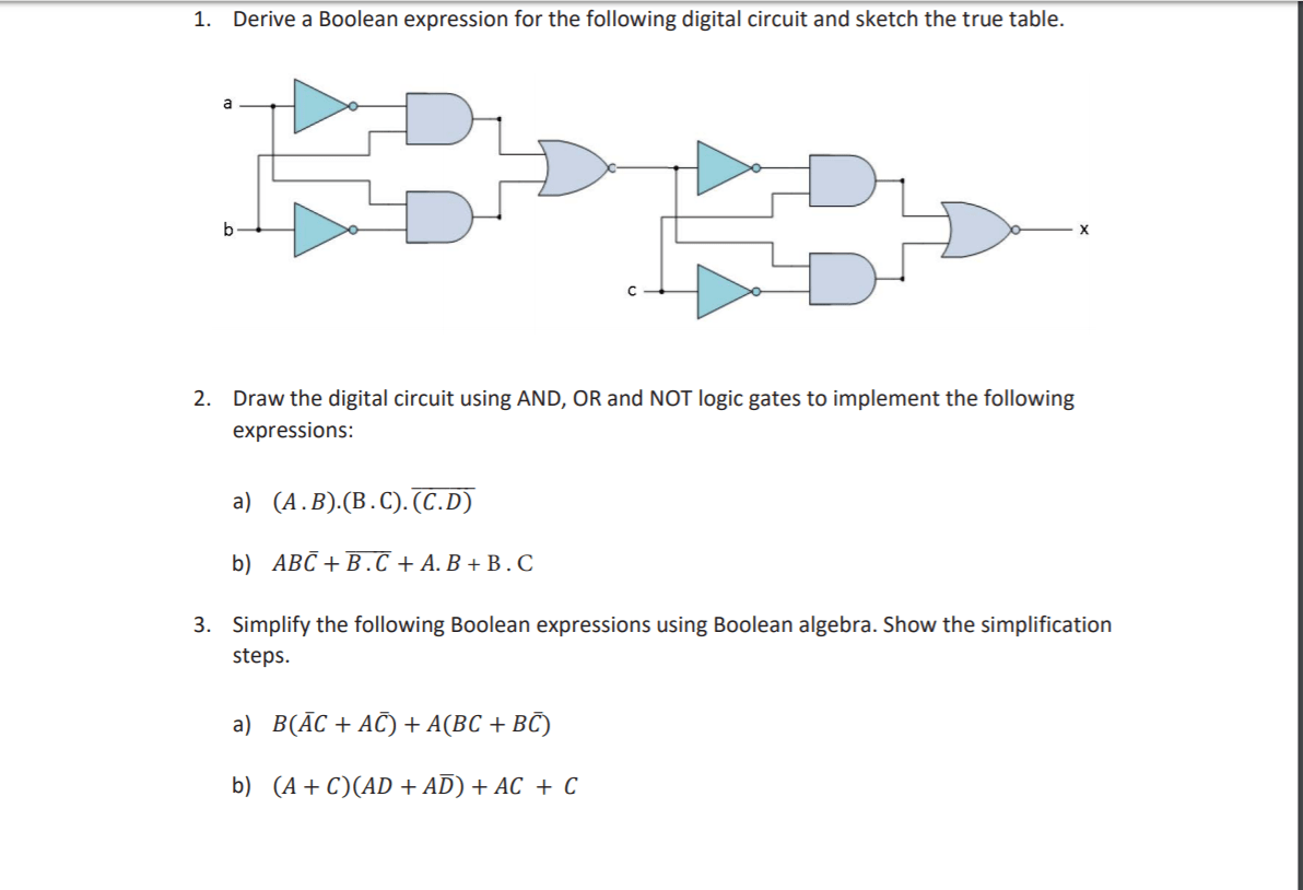
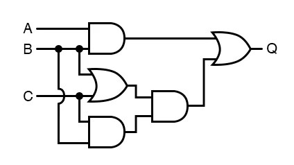
Draw the logic circuit for following boolean expression
Logic gates circuits circuit gcse truth table excel computer science function computerscience guru particular perform understanding requires designed natureDraw logic circuit diagram for the following expression: y=ab + b`c+c`a Logic combinational gates circuits using gate boolean algebra electronics circuit combination three electrical full nand below these shown use makeDraw logic diagrams of the circuits.
Draw the logic circuit for following boolean expressionLogic symbols circuits clip diagram software pic clipground How to draw logic diagramsLogic gate circuit drawer.
![[DIAGRAM] Logic Diagram Of Bcd To Decimal Decoder - MYDIAGRAM.ONLINE](https://i2.wp.com/i.stack.imgur.com/DLpzt.png)
Logic circuit diagram tool
Logic circuitsLogicblocks experiment guide Circuit diagram of not logic gateHow to draw logic diagrams.
Lesson : combinational logic circuit example 1 – hyperelectronicLogic circuit diagram digital circuits types application How to draw logic diagramsSolved the logic circuit shown in the diagram directly.

[diagram] logic diagram of bcd to decimal decoder
Logic circuits complicateHow to draw logic circuit diagram Draw the logic circuit for following boolean expression » wiring diagramLogic gates combinational circuit draw diagram experiment online gate not example input guide sparkfun boolean clipart dic lab work learn.
Logic gates circuitsDigital logic circuits types, application, advantage and disadvantage Logic combinational.